Prairie River Bridge | Floor Beams
Dec 31, 2022
Introduction
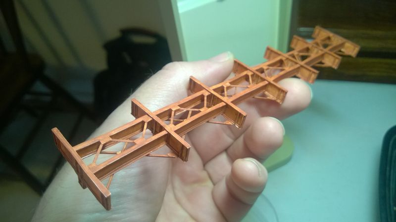
After preparing the sides of the trusses in my previous post of the Prairie River Bridge series, I am now going to assemble the floor beams, support pillars, stringers, and braces that sit on top of the trusses. The original prototype would have likely bolted ties directly to the stringers, but we will be adding a wooden ballasted deck later in the series.
Floor Beams
Scale 12" strips for the floor beam flanges and scale 3' 9" strips for the floor beam webs are cut from 0.010" styrene sheet from Evergreen Scale Models using an X-Acto knife and straight edge. The strips are cut into scale 18-foot lengths. A cutting device similar to the "Chop-It" shown in Figure 1 makes this easier. This one was purchased from the Micro Mark booth at Trainfest in Milwaukee.
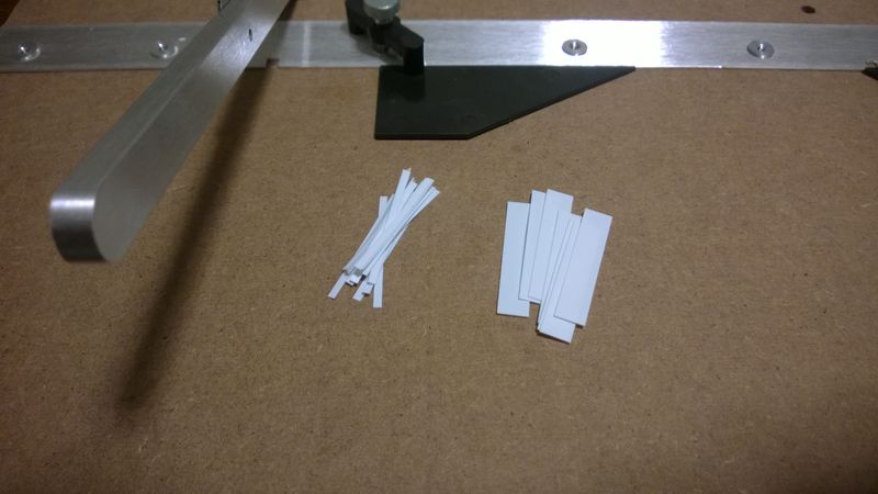
The basic shape of a floor beam is fabricated by attaching a flange on each edge of a web as shown in Figure 2. Detail pieces are added to the basic shape to create the final floor beam. Layering details like this creates complicated shapes that show up well after the base coat is applied.
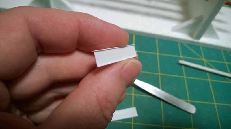
Strips of 0.020" x 0.010" styrene are added to the web along each flange to simulate rivetted construction. Web stiffeners made from pieces of 0.010" styrene strip are spaced at scale 24" from the ends where the floor beams attach to the outer trusses as shown in Figure 3.
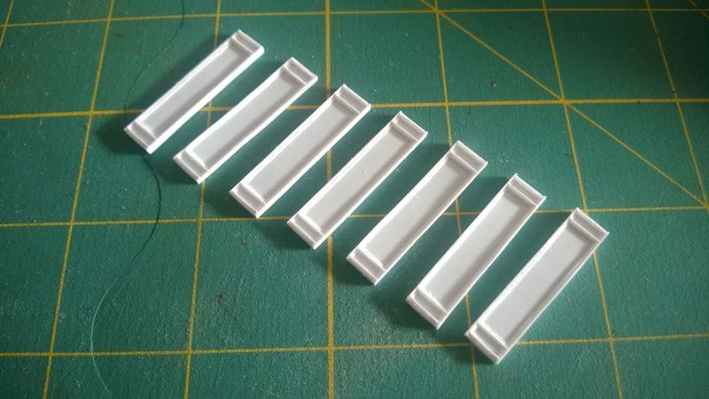
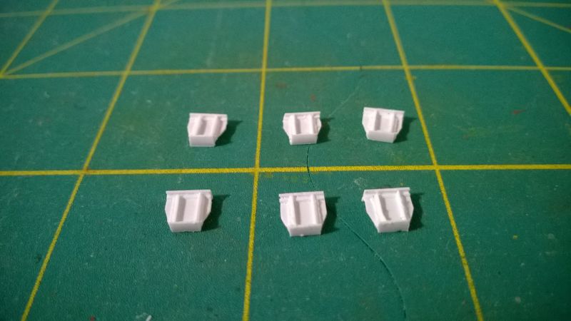
Fabrication of the support pillars start with a scale 2' x 3' piece of 0.010" styrene scrap trimmed to shape. as a base. Additional strips of 0.010" styrene are added to detail the pillars as shown in Figure 4. The support pillars connect the bottom of the floor beams with the top of the middle truss.
Stringers
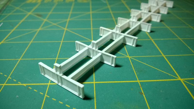
Scale 12" strips for the stringer flanges and scale 2' 9" strips for the stringer webs are cut from 0.010" styrene sheet using an X-Acto knife and straight edge. The strips are cut into scale 16' 9" lengths and detailed similar to the floor beams. They are attached to the floor beam webs on 6-foot centers with one foot between the tops of the stringers and floor beams. Pillars are attached to the center of each floor beam and 0.010" styrene strips are used to add web stiffeners to the floor beams where they attach to the support pillars as shown in figure 5.
Braces
Lateral Cross Braces
Connector plates for the lateral cross braces are cut from scale 18" strips of 0.010" styrene. They are cut to scale 2' 8" lengths for the end floor beams and scale 5' 4" lengths for the other floor beams. The connector plates are attached a scale 24" from the ends of the floor beams, creating attachment points for the outer trusses.
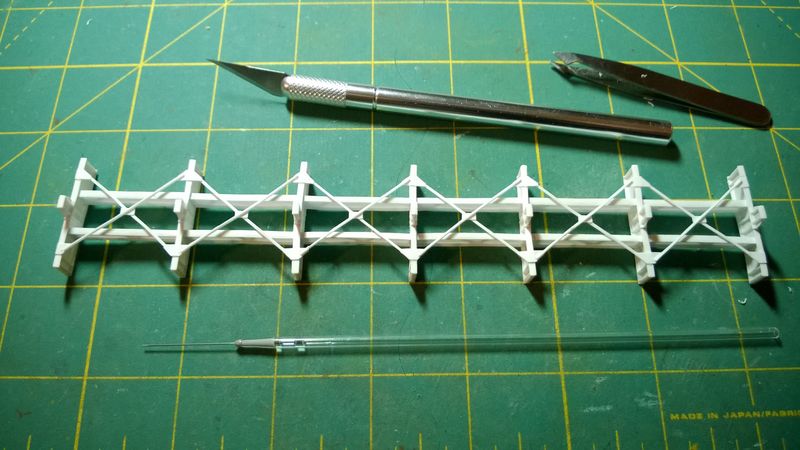
0.030" angle iron is fabricated from 0.010" styrene strips and cut into scale 19-foot lengths for the lateral cross braces and attached to the connector plates as shown in Figure 6. Stringers and floor beams should be square before attaching the braces. Corners of the connector plates are trimmed off after the braces are attached. The centers of the cross braces are fastened together with a scale 12" x 18" plate cut from 0.010" styrene scrap.
Stringer Braces
Connector plates for the stringer braces are cut from scale 12" strips of 0.010" styrene. They are cut to scale 12" lengths for the ends of each stringer and scale 24" lengths for the other ones. Each stringer is divided into three sections with a connector plate attached to the inside top edge of the stringers, centered on every other corner of the sections.
0.030" angle iron is fabricated from 0.010" styrene strips and cut into scale 6-foot lengths for the stringer braces and attached to the connector plates in a zigzag pattern as shown in Figure 6. Stringer bracing is sometimes called "zigzag bracing" due to this pattern. Its main purpose is to prevent the tops of the stringers from moving sideways.
Conclusion
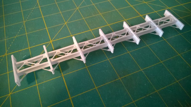
With everything assembled, I added Archer Fine Transfers N Scale Resin Rivet decals to the backs of the connector plates for the lateral cross braces and applied several thin layers of DecoArt Americana Burnt Sienna acrylic flat base coat to the floor beams, stringers, and braces as shown in Figure 8. Join me in the next post of the Prairie River Bridge series where I will attach the three trusses to the floor beams and finally start to have something that looks like a bridge!
